WIP
Author: Teresa Afonso
-
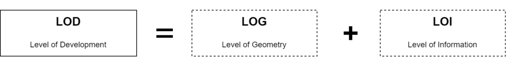
A04.01. LOD
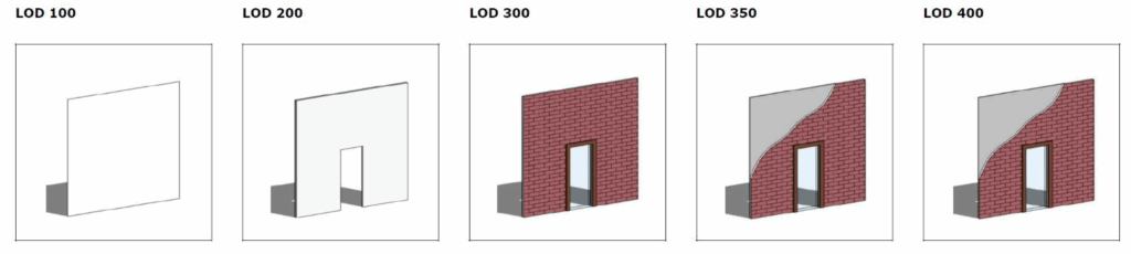
The Level of Development (LOD) defines how the geometry and information of the model can achieve different levels of refinement and it is used to measure the level of the service required.
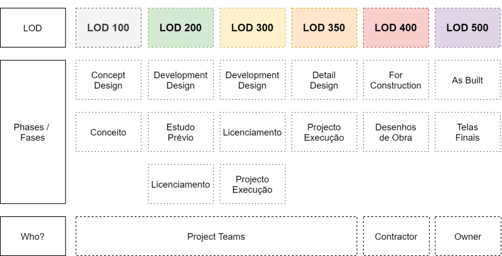
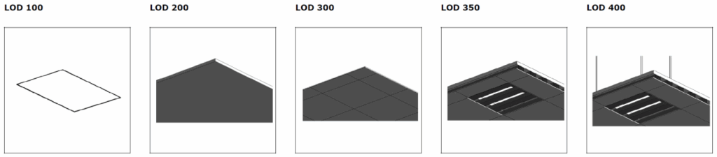
The images bellow were taken from the document “Building Component Catalogue with Level of Development Specification (LOD)” by “MTHojgaard”. They are a good example of how the LOD influences the geometry (LOG) You can find the full Document in NLA`s server in this path: P:\BIM\04_DocAux\04_LODS
“Level of Development (LOD) Specification Part I & Commentary”
For a deeper understanding of the specifications of each LOD you must consult the current level of specification document “Level of Development (LOD) Specification Part I & Commentary” by BIM Forum. You can find the document in bimforum.org/lod and in NLA`s fileserver in the path: P:\BIM\04_DocAux\04_LODS
The following definitions were taken from the document:
LOD 100
“The Model Element may be graphically represented in the Model with a symbol or other generic representation but does not satisfy the requirements for LOD 200. Information related to the Model Element (i.e. cost per square foot, tonnage of HVAC, etc.) can be derived from other Model Elements.”
LOD 200
“The Model Element is graphically represented within the Model as a generic system, object, or assembly with approximate quantities, size, shape, location, and orientation. Non-graphic information may also be attached to the Model “
LOD 300
“The Model Element is graphically represented within the Model as a specific system, object, or assembly in terms of quantity, size, shape, location, and orientation. Non-graphic information may also be attached to the Model Element.”
LOD 350
“The Model Element is graphically represented within the Model as a specific system, object, or assembly in terms of quantity, size, shape, location, orientation, and interfaces with other building systems. Non-graphic information may also be attached to the Model Element.”
LOD 400
“The Model Element is graphically represented within the Model as a specific system, object, or assembly in terms of size, shape, location, quantity, and orientation with detailing, fabrication, assembly, and installation information. Non-graphic information may also be attached to the Model Element.”
Example –Light Fixture:- LOD 100 – cost/sf attached to floor slabs
- LOD 200 – light fixture, generic/approximate size/shape/location
- LOD 300 – Design specified 2×4 troffer, specific size/shape/location
- LOD 350 – Actual model, ‘Lightolier’ DPA2G12LS232, specific size/shape/location
- LOD 400 – As 350, plus special mounting details, as in a decorative soffit
Copyright © 2015 by BIMForum. All rights reserved
-
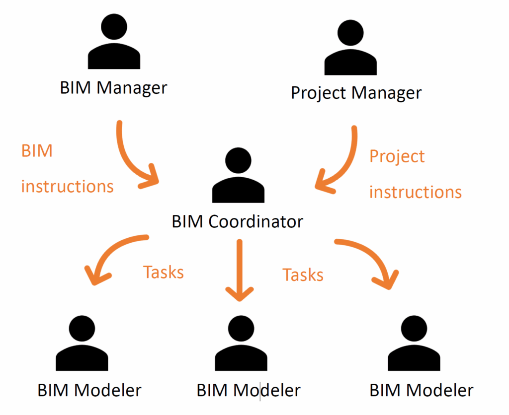
A03. Teams’ Dynamics
The workflow of communication and information sharing should proceed according to the diagram bellow, in order to allow a proper workflow. It is mandatory that project decisions are transmitted from the project manager to the BIM coordinator which, with his BIM knowledge and alongside with advice from the BIM manager, will define priorities, tasks and assignments to modellers.
The level of knowledge and capacity of each team member should also be taken into account.