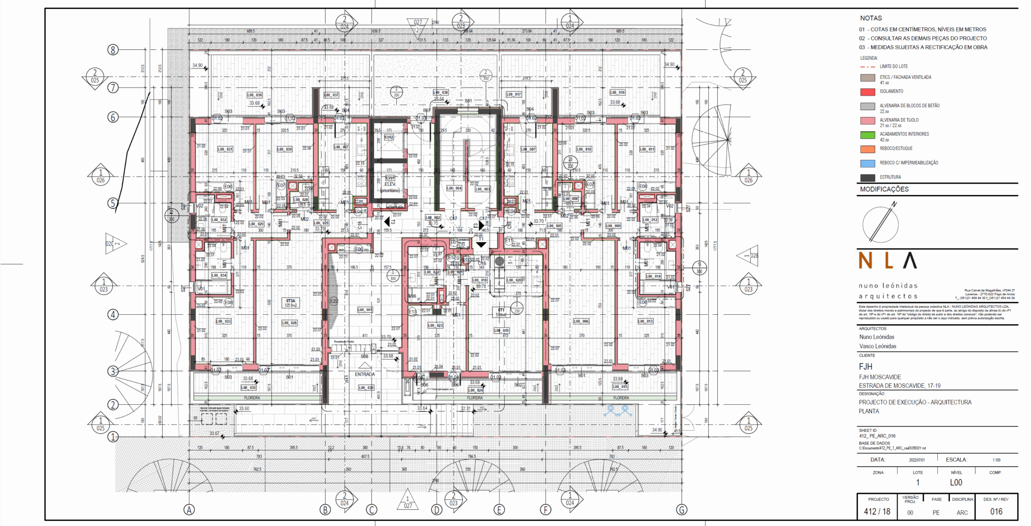
In the general floor plans, all the construction elements must be represented, properly tagged and identified: stairs, walls, finishes, doors, windows, sections, elevations, grids, dimensions, identification of enlarged areas.
In the general floor plans, all the construction elements must be represented, properly tagged and identified: stairs, walls, finishes, doors, windows, sections, elevations, grids, dimensions, identification of enlarged areas.
In a project phase, there will be versions of the project, first emissions of sheets and revisions’ sheets.
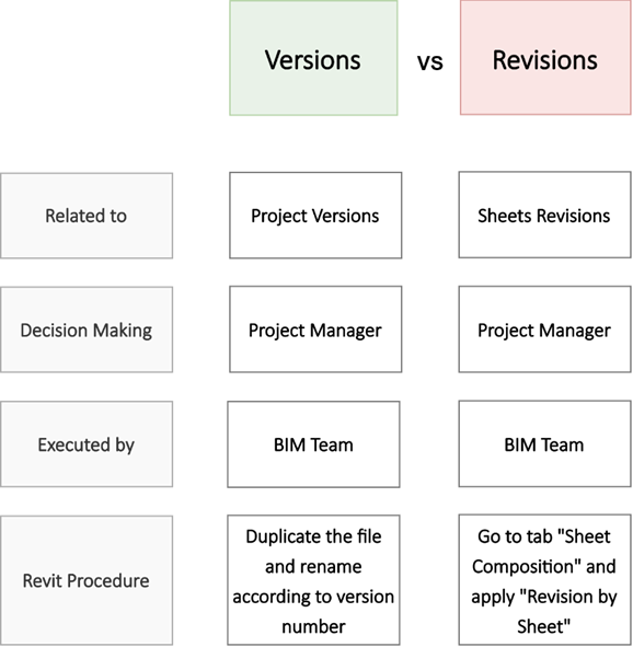
Revisions:
The changes reflected in a drawing have a revision number, that is identified in the sheet. The description of the revision is included in the legend of the sheet.
Versions
When there are several changes / revisions, it might be necessary to issue a new version of the project. This decision is made by the Project Manager. A new copy of the file must be created.
NOTE: The sheet list can be issued several times, with the new revisions of the sheets, but this does not mean that it is necessarily a new version of the project.
| 3×1 | 3×1.5 | 3×2 | 3×2.5 | |
| 580×297 | 580×446 | 580×594 | 580×743 | |
| 4×1 | 4×1.5 | 4×2 | 4×2.5 | |
| 765×297 | 765×446 | 765×594 | 765×743 | |
| 5×1 | 5×1.5 | 5×2 | 5×2.5 | 5×3 |
| 950×297 | 950×446 | 950×594 | 950×743 | 950×891 |
| 6×1 | 6×1.5 | 6×2 | 6×2.5 | 6×3 |
| 1135×297 | 1135×446 | 1135×594 | 1135×743 | 1135×891 |
| National (PT) | International (ENG) | ||
| Code | Description | Code | Description |
| COR | Coordenação | CRD | Coordination |
| TOP | Topografia | TOP | Topographical |
| URB | Urbanismo | URB | Urbanism |
| PAI | Paisagismo | LDS | Landscaping |
| ARQ | Arquitectura | ARC | Architecture |
| INT | Design De Interiores | INT | Interior Design |
| FND | Fundações | FND | Foundations |
| EST | Estrutura | STR | Structural |
| MEP | Mep | MEP | Mep |
| MEC | Mecânica | MEC | Mechanical |
| AVAC | Avac | HVAC | Hvac |
| ELE | Electricidade | ELE | Electrical |
| TUB | Tubagens | PLU | Plumbing |
| HID | Hidráulica | HYD | Hydraulic |
| DRN | Drenagem | DRN | Drainage |
| ILU | Iluminação | LGH | Lighting |
| TEL | Telecomunicações | TEL | Telecom |
| SEG | Segurança (Cctv) | SEC | Security (Cctv) |
| SCI | Segurança Contra Incêndios | FLS | Fire And Life Safety |
| ACT | Acústica | ACT | Acoustic |
| TER | Térmica | THR | Thermal |
| GAS | Gás | GAS | Gas |
| LIX | Lixo | GRB | Garbage |
| SIN | Sinaléctica | SGN | Signage |
| ELV | Elevadores | ELV | Elevators |
| PIS | Piscinas | PWF | Pools |
| HOS | Hospitalidade – Operações | HOS | Hospitality – Operations |
| DML | Demolições | DML | Demolitions |
| TMS | Technical Management System | ||
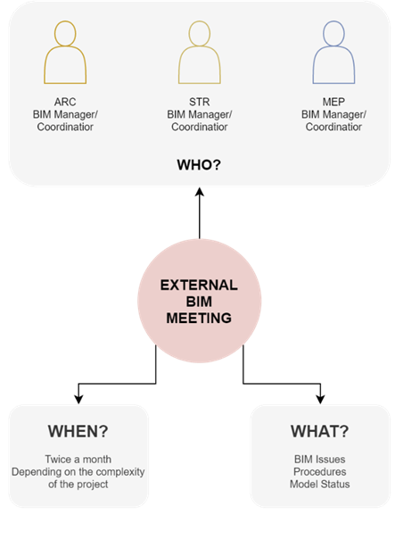
All the internal meetings should be as quick as possible. If they get to long and too frequent, the time available to actually work will not be enough and delays can happen.
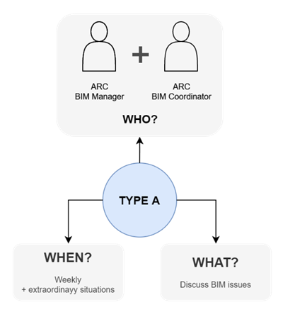

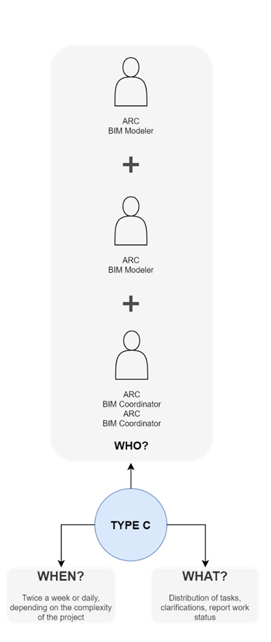
It is important that all participants in the meeting have actual BIM knowledge, because otherwise people who are not up to the topic may commit with
impossible tasks or deadlines.
Copyright:
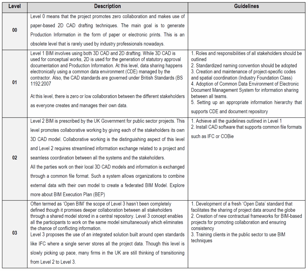
This table was created according to the document “BIM Maturity Levels Explained- Level 0 | 1 | 2 | 3” – United BIM.
The copyrights of all the text used in this table belongs to United BIM.
https://www.united-bim.com/bim-maturity-levels-0-level-1-level-2-level-3/
WIP
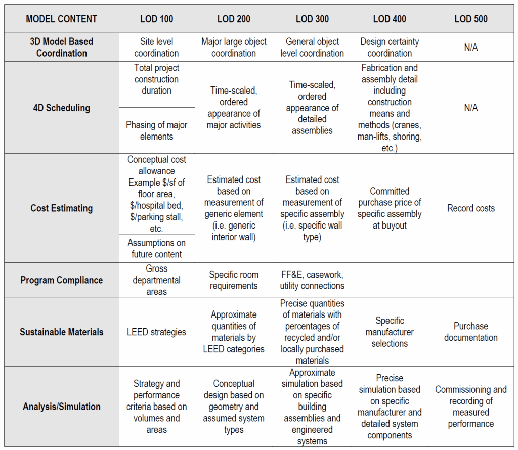
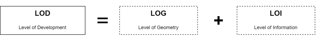
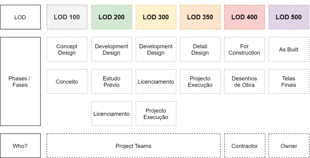
The Level of Development (LOD) defines how the geometry and information of the model can achieve different levels of refinement and it is used to measure the level of the service required.
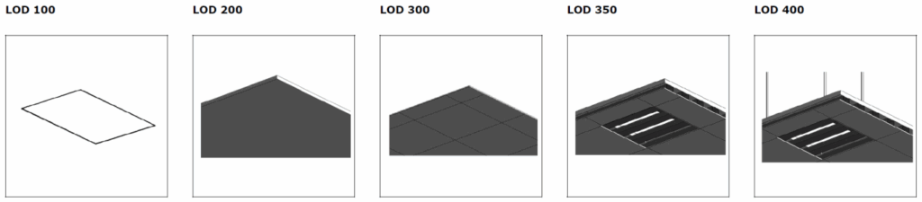
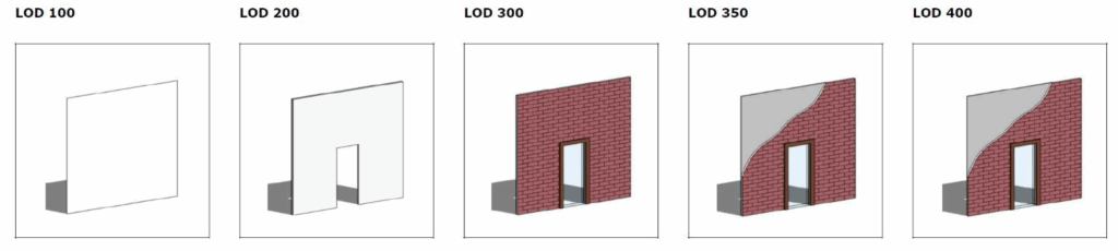
The images bellow were taken from the document “Building Component Catalogue with Level of Development Specification (LOD)” by “MTHojgaard”. They are a good example of how the LOD influences the geometry (LOG) You can find the full Document in NLA`s server in this path: P:\BIM\04_DocAux\04_LODS
“Level of Development (LOD) Specification Part I & Commentary”
For a deeper understanding of the specifications of each LOD you must consult the current level of specification document “Level of Development (LOD) Specification Part I & Commentary” by BIM Forum. You can find the document in bimforum.org/lod and in NLA`s fileserver in the path: P:\BIM\04_DocAux\04_LODS
The following definitions were taken from the document:
LOD 100
“The Model Element may be graphically represented in the Model with a symbol or other generic representation but does not satisfy the requirements for LOD 200. Information related to the Model Element (i.e. cost per square foot, tonnage of HVAC, etc.) can be derived from other Model Elements.”
LOD 200
“The Model Element is graphically represented within the Model as a generic system, object, or assembly with approximate quantities, size, shape, location, and orientation. Non-graphic information may also be attached to the Model “
LOD 300
“The Model Element is graphically represented within the Model as a specific system, object, or assembly in terms of quantity, size, shape, location, and orientation. Non-graphic information may also be attached to the Model Element.”
LOD 350
“The Model Element is graphically represented within the Model as a specific system, object, or assembly in terms of quantity, size, shape, location, orientation, and interfaces with other building systems. Non-graphic information may also be attached to the Model Element.”
LOD 400
“The Model Element is graphically represented within the Model as a specific system, object, or assembly in terms of size, shape, location, quantity, and orientation with detailing, fabrication, assembly, and installation information. Non-graphic information may also be attached to the Model Element.”
Example –Light Fixture: